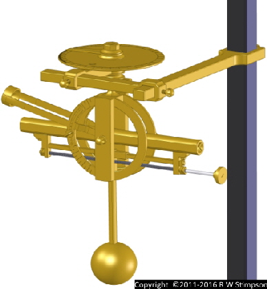
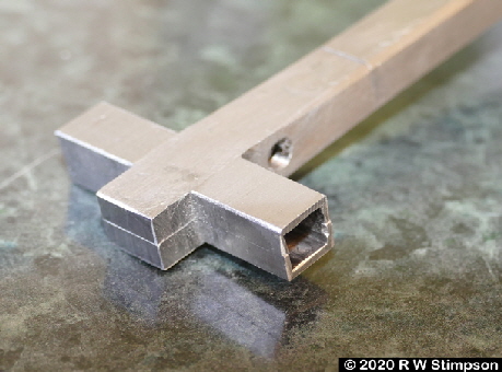
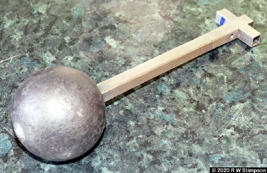
The counterbalance ball in this replica is adapted from a cast steel decorative gate accessory, drilled and then riveted into position on the counterbalance ball shaft. At the top end, the slider guide for the square shaft was created from two identical machined cruciform-channel parts which were riveted onto the top end of the ball shaft. This had been reduced in size from the 3/8in of the shaft to 1/4in square. The rivets were countersunk headed and then filed flush with the sides. The adjustment screw thread hole was drilled and tapped after riveting, which took place with a 1/4in square stock bar in place within the recess to ensure it did not bind. As with many of these parts, it still requires finishing and polishing to remove surface defects and the visible engineer’s blue!
April 2020 Trial Assembly (right)
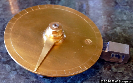
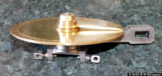
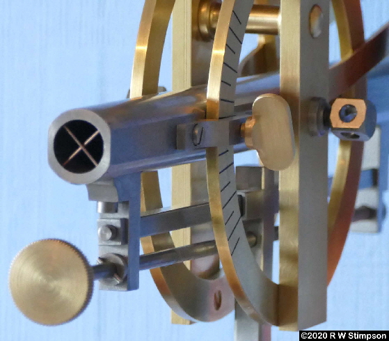
Here we see the top alignment protractor and pointer fitted up to the azimuth yoke with the sight tube and depression counterbalance weight.
A lot of filing, polishing with steel wool and varnishing are now to follow to finish the parts to a high standard!
It will also need a transportation box!
Full-size Replica Functional Marine Theodolite
Work completed up to Summer 2020
May 20th 2020 Update:
Project Completed!
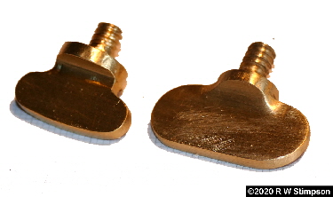
The final two components - the locking thumb-screws for the eyepiece support and the main sight tube have each been cut and filed to size from solid pieces of brass 1” x 1/2” x 1”. The threaded screw was filed down gradually to fit into a 6mm, 5mm, 4mm then 3.5mm hole in a template - allowing the 3/16in BSW die to finally cut the required thread.
Total hours worked to date: approximately 290
April 2020 Update:
Progress - Sadly Interrupted!
Progress over the past Autumn 2019 and Spring 2020 academic terms at the William Kennish Engineering Centre has been good - I was hoping to even finish the construction stage of the theodolite, but the Covid 19 emergency put paid to that, losing the last two evenings of the extended evening class (night school) which College IOM had very kindly agreed to put on for me and six other like-minded adult students.
This part of the web site has also been updated to now show the development of the full-size working replica Kennish Marine Theodolite over the intervening years. Each winter and spring term was 9 evenings of 3 hours - so 54 hours work per year.
I sincerely offer everyone viewing this page good health and best wishes at this challenging time.
Component Parts
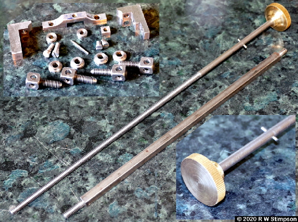
Diagonal across the centre is the counterbalance adjustment screw with 3/16in BSW thread and straight-knurled brass end knob. This was turned, knurled, drilled, bored and then parted prior to being push-fitted to the screw. Interference was 0.05mm.
The taper-pin shown fitted was inserted, pressed in place then cut to size. See the longer pin in the centre of the other parts photo. Undercut tip is at the larger end; this will only be fitted and cut on final assembly.
Parts visible from the top left are: left and right counterbalance bar L-brackets, elevation lock-screw saddle, counterbalance adjustment screw spacer washers (2), counterbalance square shaft retaining square nut, two L-bracket 3/16in BSW retaining screws, taper pin, azimuth saddle retaining screws (2), four pivot screw locking nuts, four pivot screws.
All screws are hand made specifically for the project.
Challenging parts!
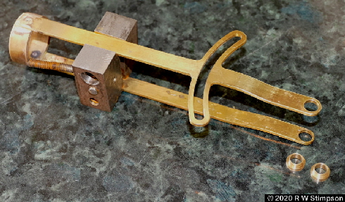
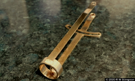
This (right) is the partly completed eye-sight guide which is shown clamped in a steel assembly clamp jig. The jig will be unbolted and discarded after silver soldering has been completed.
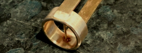
The sight guide comprises four parts: a central turned eye piece ring, a locking screw guide arcuate side, a second plain support side and a cross-hair. The latter is made from 1.6mm diameter welding wire!
The threaded bent parts are just eye ring jig supports to ensure it keeps the eyepiece satisfactorily square to the sides. The two turned brass spacers shown will ensure this asssembly is placed at the correct location on the sight tube pivot pins.
The image below shows the jig, the silver soldering rig with vermiculate heat-reflecting blocks - these worked superbly well and allowed the soldering to be completed with a domestic plumbing butane/propane blowtorch with a screw-in canister.
The brass pivot guides were adjusted to ensure the eyepiece alignment screw arcuate slot lined up correctly with the housing, then individually silver soldered in place.
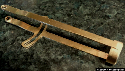
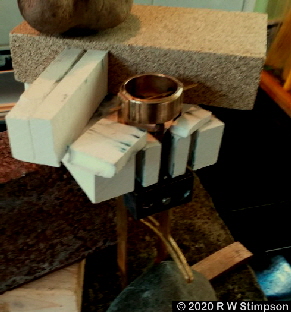
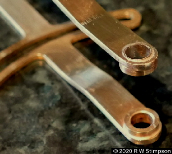
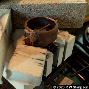
Silver solder (Silverflo 40) melts at 660-710°C (1220 - 1310°F) which is around three times the 220°C (428°F) that soft solder melts at - so the vermiculate insulating blocks were critical in getting the heat into the brass parts. Side arms are 2mm (5/64in) thick; ring is 25.4mm (1”) internal diameter. End was then placed in jeweller’s pickling solution at 80°C for 1/2 hour.
Full Assembly (right)
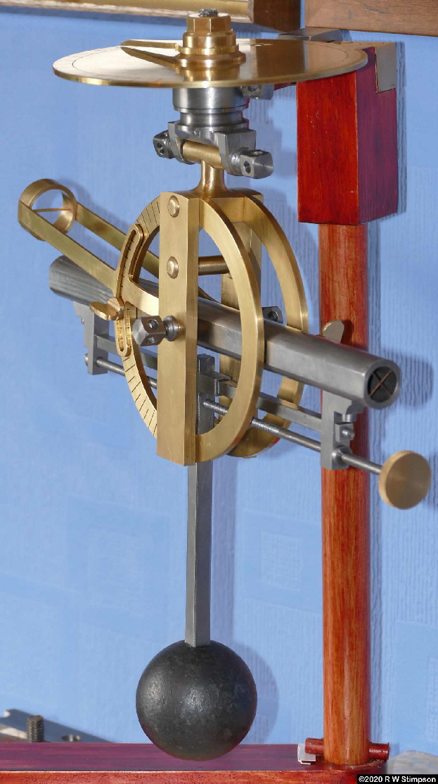
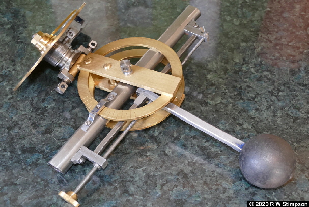
View right is of the assembled theodolite fitted to a simple timber support stand.
After filing and work with emery cloth to remove scratches, all parts were buffed with wire wool before final finishing with Restoration Wax - a polish for all materials originally developed by the British Museum and available on the web - a superb non-corrosive material!

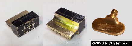
May 2020 Thumb screw manufacture (above)
The two screws were cut and filed from brass blocks due to the cancellation of classes at the William Kennish Centre due to the pandemic. After marking out some key fillet radii were created by drilling through the blocks. Filing and cutting then continued to create the remainder of the features using the drilled radii as reference points.
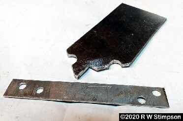
The filing guides shown below were cut from aluminium sheet - the arcs from drilled holes in the upper plate used for the screw bosses and the four holes in the lower template used to file 3/16in dia screw blanks accurately and gradually from the parent block.
Full Assembly wiewed from the back (above)

Site Copyright Statement © 2011-2022 Robert W Stimpson


